- 01: Intro →
- 02: Site Preparation →
- 03: Verify the Height of the Ledger Board →
- 04: Layout of Ledger and Front Rim with Breaker Board →
- 05: Determine Guardrail Post Location →
- 06: Determine the Joist Locations →
- 07: Prepare Ledger Board for Fasteners →
- 08: How to Attach Flashing to Ledger Board →
- 09: Attach the Ledger Board →

What is a Deck Ledger Board?
A deck ledger board is the framing component that anchors the frame of a deck to the house. It provides a solid connection point for the deck joists and helps transfer the load of a deck into the structure of a home. Because it supports a large portion of a deck’s weight, proper ledger board attachment is essential for the safety of any deck.
Ledger boards are typically made from the same material and size as the joists and must be installed with approved structural fasteners that are spaced in a specific pattern spelled out by building codes. Equally important, flashing should be installed above, behind and sometimes below the ledger board to prevent water from getting behind the cladding and into the wall assembly. Proper flashing and attachment help prevent rot and water damage, both of which can compromise the ledger-house connection and cause a deck to fail. Learn more about the other deck components here.
Tools for Deck Ledger Installation
- Driver & Bits: Used to drive structural screws, lag bolts, or other fasteners when securing the ledger board to the house, an essential step in how to secure a deck to a house.
- Circular Saw: Used to cut the ledger board to length and make clean, square cuts for a tight fit against the house.
- Chalk Line: Used to snap straight layout lines on the wall or sheathing to mark the location of the ledger.
- Ratchet Wrench and Sockets: Used when using through bolts to secure a ledger.
- Hammer: Used to drive nails or tap the ledger and flashing into position before fastening.
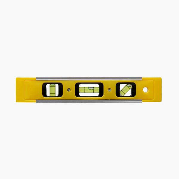
- Level (at least 4 ft.): Used to ensure the ledger board is perfectly level along its full length and lines up with the beams when attaching a deck to a house.
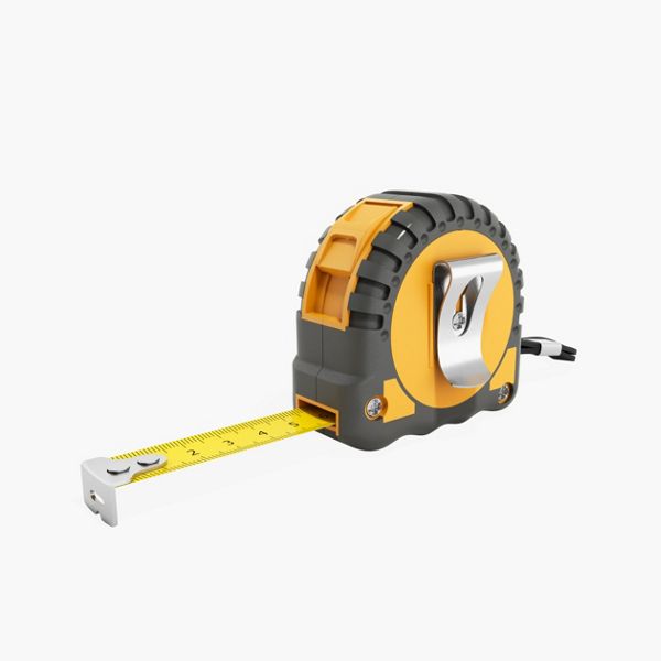
- Tape Measure: Used to measure distances for placement, layout, and spacing of fasteners along the ledger.
- Metal Snips: Used to cut aluminum or steel flashing to the correct length and shape before installation.
- Pencil: Used for marking measurements and layout lines on the wall and ledger board.
- Speed Square: Used to make quick, accurate perpendicular or angled cuts and layout marks on the ledger.
- Framing Square – Used to verify square corners and check alignment between the ledger and adjoining framing when connecting a deck to a house.
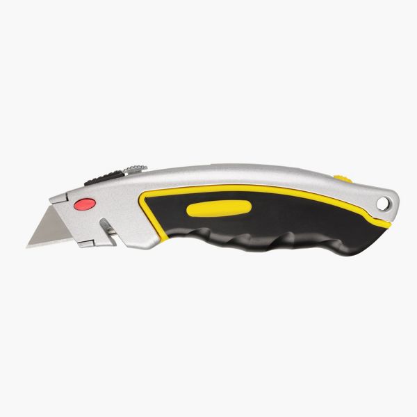
- Utility Knife: Used to trim the Weather-Resistant Barrier (WRB) or siding where the ledger and flashing will be installed.
- PPE: Gloves, Safety glasses, Hearing protection: Used to protect hands, eyes, and ears during cutting, drilling, and fastening.
Materials for Deck Ledger Installation
- Pressure-Treated Wood: Used for the deck ledger board, which supports the ends of the deck joists. Pressure-treated lumber resists rot and decay, ensuring a long-lasting connection when attaching the ledger board to the house. It should be the same dimension as the joists for a flush, even installation.
- Fasteners: Structural screws should penetrate the home’s interior framing to provide a solid mechanical connection. If you have access to the inside framing, through bolts with nuts and washers are another reliable option. All fasteners must be corrosion-resistant, such as hot-dipped galvanized or stainless steel, to ensure durability during deck ledger board installation.
- Metal Flashing: Installed above the ledger board to prevent water from getting behind it and causing rot. Use corrosion-resistant aluminum or galvanized steel flashing. Keep in mind that aluminum cannot come in direct contact with treated wood, so some sort of barrier like flashing tape will need to separate the two.
- Back Flashing: Installed behind the ledger board, back flashing provides a secondary layer of protection against moisture. It helps prevent any water that slips past the top flashing from penetrating the wall assembly and causing damage behind the ledger.
- Flashing Tape: Self-adhering flashing tape seals the tops of the metal flashing, ledger and joists, protecting screw penetrations from moisture intrusion. It’s an added layer of defense that extends the life of your framing components.
- Weather-Resistive Barrier (WRB): A continuous membrane installed over wall sheathing to prevent water from entering the home. The WRB should overlap the top of the ledger flashing to maintain a proper drainage plane and protect the building envelope during how to attach deck to house projects.
- WRB Seam Tape: Used to seal seams and overlaps in the weather-resistive barrier. Properly taping WRB joints ensures a continuous moisture barrier, which is critical for preventing water infiltration behind the ledger area.
Deck Ledger FAQs
How to attach a deck ledger to siding?
You should never attach a ledger board over siding or directly to cladding materials such as brick. Specialty spacers can be used to hold the ledger away from the siding, and structural fasteners are available for securing a ledger to the house framing when brick is present. However, if you do not plan to remove the existing siding, consult your local building official before beginning installation. In most cases, the siding must be removed and then reinstalled using proper flashing techniques. Learn more about how to remove and replace siding here.
What do you put behind a deck ledger?
When attaching a ledger board to a house, a waterproof barrier, often called “back flashing,” should always be installed between the ledger and the wall to protect against moisture damage. One popular option includes a self-adhesive flashing membrane like ledger tape, which seals fastener penetrations and helps prevent water from reaching the sheathing.
Can a deck ledger board be attached to studs?
A deck ledger board should never be fastened directly to wall studs. For a safe and code-compliant connection, the ledger must be anchored through the wall sheathing and into the house’s rim or band joist. A rim joist provides the strength needed when connecting a deck to a house, ensuring the deck can safely carry its load. If the section of the wall where you want to install the surface of the deck has no rim joist, common on multi-level decks, you can either have an engineer design a plan or install extra posts and create a freestanding deck close to the surface of the wall.
Common Mistakes and How to Avoid Them
Proper ledger board attachment is one of the most important steps when building a deck. It’s also one of the stages most prone to mistakes. Here are a few issues to watch for.
- Attaching to the Wrong Part of the House: Never fasten a ledger board to wall studs or over siding. The ledger needs to anchor through the sheathing and into the home’s rim or band joist, which provides the structural strength to support the deck. If your framing doesn’t allow for that, build a freestanding deck instead. It’s the safest and most code-compliant option.
- Skipping or Misplacing the Flashing: Here’s the correct flashing sequence: Install back flashing on the wall → Add flashing along the bottom of the ledger location (only if there’s cladding below the ledger) → Fasten the ledger board → Add metal flashing on top → Apply flashing tape over the metal flashing → Overlap the WRB over the flashing tape → Seal the WRB to the flashing tape with seam tape
- Using the Wrong Fasteners or Spacing: Ledger boards must be secured with structural screws or through-bolts that penetrate the house rim joist. Avoid nails or standard deck screws because they don’t provide enough holding strength and can loosen over time. Always follow the building code or the fastener manufacturer’s guidelines for spacing and embedment depth to ensure a safe, code-compliant connection. Find out more about ledger fasteners here.
- Forgetting Long-Term Water Management: Even the best installation can fail if water is allowed to collect above or behind the ledger. Keep the area clean and make sure water drains away from the deck and house. Inspect flashing and sealant occasionally to maintain a tight barrier.
Overlooking Design and Planning Details: Good deck design starts long before you attach the ledger board. Think about how you’ll use the space—entertaining, dining, or relaxing—and make sure the deck’s size, layout, and location fit your lifestyle. Taking your time to plan helps ensure the finished deck looks great and functions the way you want. Discover more considerations when building a deck.
So you're ready to get started? Watch our how-to tutorial before you start your build.
Before you begin any DIY project, make sure to wear the appropriate personal safety equipment. Eye protection, ear protection, gloves, long pants, a long-sleeved shirt, and reinforced toe shoes are recommended. Always make sure that you have a first aid kit nearby. For any home project, be certain to follow local code and permitting requirements.
Step 1: Remove Siding of House
The siding on the house will need to be removed before installing the deck ledger board. Make sure to remove enough siding to be able to install the back flashing above the ledger board and below the ledger board. This will vary per municipality so check with the local jurisdiction in the area for specific dimensions. In this case the numbers were 6” above the ledger and 3” below the ledger. More siding was removed in this case due to the rot found in the sheathing. Once the sheathing was replaced, back flashing was installed to preserve the life of the new sheathing.

Step 1: Determine Placement of the Joist
Place a joist on top of the beams and pull it tight to the wall of the house. Place a level on top of the joist and make sure the joist is level. The top of the joist should align with the mark made when the beams were installed.

Step 2: Repeat Process
Repeat this process on each end of the deck giving three marks along the house notating the top of the ledger board.

Step 3: Snap a Chalk Line
Snap a chalk line along the house using the three marks made earlier. To do this with one person, place a screw at one of the marks on the end of the deck.

Hook one end of the chalk line on the screw and pull the line across to the other side of the deck. Hold the line tight and pull the line out away from the house with the opposite hand. Let the line go to snap the line. Do this two times to ensure all areas are marked with the chalk.

Layout of the ledger is the process of marking where the joists, guardrail posts, stairs and any other accessories will go. It is important to do this process first to make sure these pieces do not interfere with each other. In the case where the pieces do intersect, they can be adjusted in the planning process. If proper planning is not taken during this step, you may need to disassemble and move pieces later, which will extend your timeline and budget.
Step 1: Determine Length of The Front Rim Joist and Ledger Board
The first step is to get the length of the front rim joist and ledger board. The front rim joist will be the same length as the beam that was installed. For a refresher on the beam installation, check out our guide on "How to Install Deck Frame Beams and Posts."
This measurement can be verified by measuring against the house where the deck ledger board will be placed. The ledger board will be 3” shorter than the front rim joist. This is to allow the side rim joists, which are 1 ½”, to overlap the ledger board and connect through the joist and into the ledger board. The side rim joist will connect with the front rim joist overlapping it.

Place the ledger board and the front rim joist on top of the beam, or a set of sawhorses can be used. This puts the ledger board and front rim joist in the correct position of how they will be placed on the deck frame so that the marks are visible. Place the ledger board 1 ½” in on each side from the front rim joist and in the vertical position.

Step 2: Mark the Accessory Placement
The accessories need to be marked next. In this case the main accessory will be the breaker board that goes down the middle of the deck. Breaker boards can be used when the deck is longer than 20’ and multiple shorter pieces of decking have to be used. The breaker board gives a pattern design to the decking and eliminates multiple seems throughout the deck. Breaker boards can also be used on shorter decks as a design feature. In this case the breaker board is due to the deck being longer than 20’. To determine where the breaker board will be placed, measure on top of the ledger board and front rim joist to find the center point of the deck.

Using the center line, mark 2 ¾” to each side of the line. This will give 5 ½” total which is the width of a decking board. That will put a joist at each side of the decking board to support it.

Extend the lines on to each of the ledger boards and the front rim joist.

Measure in from those lines 1 ½” on each side. Extend the lines through both boards and place an "X" in between the lines. This shows where the joists will be placed.

These two joists will support the decking breaker board.

The breaker board will have decking boards perpendicular to it. This means that those deck boards will have to be supported on the ends. This will be done by placing a joist next to the breaker board joist. It is good practice to leave ½” in between the joists to let water and debris flow between them. If the joists are tight together then rot can occur and reduce the life of the deck frame. To place these joists, measure ½” from the breaker board joist and make a mark.

Next, mark 1 ½” from that mark and put an "X" in between the lines. This is where the joist will be placed.

These joists will support the decking board ends that meet the breaker board.

Now, it is time to mark out the location of the guardrail posts. Marking the guardrail posts will ensure that they do not hit any joists making the install quicker and simpler.
Step 1: Mark the Post at One End of the Deck
Start by marking a post at the end of one side of the deck. This mark will be on top of the ledger board and front rim joist. Remember to place the guardrail post 1 ½” inside the edge of the deck. The side rim joist is there, and the post will need to be inside that joist.
Pro Tip
Small pieces of 4x4 can be cut to place in the guardrail post locations as a visual.

Step 2: Account for Stairways
In this case, there is a stairway on the end. There will be a post on the edge of the stairway, so measure the distance from the end of the deck frame. This measurement will be listed on the plans. In this instance, 45” was measured from the edge of the deck frame. This will also be the inside edge of the next guardrail post.

Mark where the post will be placed, then mark the center of the post. 4x4s are 3 ½” wide so the middle of the post will be 1 ¾”. Once the center is marked, a screw can be fastened at that mark to hold the tape measure.

Step 3: Mark the Post at The Opposite End of the Deck
Mark the center of the post at the other end of the deck frame and measure between the two posts. Place the tape measure on the screw fastened to the center point of the first post. Pull the tape and measure to the center of the end post. The center points of the posts are important as the next measurements will be to the center of all posts. Doing this allows for just one measurement instead of having to measure to each side of the post.

Step 4: Determine How Many Railing Sections are Needed
Now, divide that measurement to find how many sections of rail there will be. The guardrail being used will determine how far the posts can be placed apart. Check with the railing manufacturer and the local municipality for specifications and codes for guardrails. The guardrail in this project is Trex Select® Railing and has a max span of 72”. The posts cannot span more than 72” in between the edges of the posts. In this case, the measurement was 205 ½”. 205.5 will be divided into equal sections that need to be under 72”. First attempt was 205.5/4=51.375. That means that there would be 4 sections that measured center to center 51.375”.
Another try was made to see if the number of rail sections could be reduced to 3. 205.5/3=68.5. This gave 3 sections of rail at 68 ½”. Since 68 ½” is under the max span of 72”, reducing the number of sections to 3 instead of 4 will work.

Step 5: Mark Remaining Guardrail Posts
Start at the center of the end post and measure 68 ½”. Mark this point and repeat until the other end of the deck is reached.

Step 1: Confirm Decking Span Distance
With the breaker board and guardrail post locations established, the joists can now be located and marked. Joist on center placement is based on the ability of the decking to span a certain distance. Check with the decking manufacturer to verify the spanning distance. In this case, Trex Enhance® decking will be used. Trex Enhance® decking can span 16” on center for the joists when the decking is run perpendicular, 90 degrees, to the joists. That means that in between the joists would be 14 ½”. At no point can there be a span of more than 14 ½”. There can be less as some joists will end up close together but none of them will be more than 16” on center. Decking can be placed diagonally on the deck. In this situation, check with the manufacturer’s install guide to determine what the maximum span is for diagonal decking. The spans will differ based on 60-, 45-, and 30-degree angles. For this project, we used the Trex Installation Guide to confirm our span. In this case, the joist will be marked at 16” on center as the decking is perpendicular to the joists.
Step 2: Mark Joist Placement
Hook the tape measure on the end of the front rim joist and pull the tape measure along the front rim joist to see where the joists will be at 16” on center. When the guardrail post is present, make sure that the post is in between the joists when they are placed 16” on center.

If the post is in between the joists, keep measuring to the next accessory. In this case, the next guardrail post and the joists for the breaker board are in the same area. The joists at 16” on center, the red marks on the tape measure, and the post do not intersect. The joists for the breaker board and the next joist in line end up being less than 16” on center so there is no conflict with this post and joist. Keep measuring the joists to the next post.

Step 3: Adjust Joist Placement in Cases Where it Overlaps with a Guardrail Post
At this location, the post is in the same location as the joist. To avoid the post and joist hitting each other, the joist is moved to the side of the post where the tape is coming from. That means that the distance from the moved joist to the previous joist will be less than 16”.

Restart the process by hooking the tape measure on the edge of the moved joist and measuring 16” on center for the rest of the joists. In this case the remaining joists did not interfere with any more posts.

With any interference moved to the side, the joists can now be marked on to the ledger board and front rim joist. Hook the tape measure and pull it along marking every 16” on center and then marking an X next to the line. If the tape is being pulled from left to right, mark the line, and then place the X on the right side of the line. If the tape is being pulled from right to left, mark the line, and then place the X on the left side of the line. Once all the joists have been marked on the top of the ledger board and front rim joist, transfer the lines down the face of the boards.

Fastening the ledger to the house is a critical connection. This connection holds up the entire deck, so the placement and type of fasteners used are very important.
Step 1: Check with your Local Municipality
Check with the local municipality for the placement of the fasteners and the types of fasteners that are approved. In this situation, two fasteners are started at 2” from the end of the ledger board.

These two fasteners will also have to be spaced appropriately top to bottom. In this case, the top fastener needs to be 2” from the top of the board. The bottom fastener needs to be at least 4 ½” away from the top of the ledger board. It also has to be more than 2” from the bottom of the board. In this case, the bottom fastener was placed at 5 ¼” which met both of the specifications.

These fastener placements will be different depending on the size of the material used, 2x8, 2x10, 2x12 etc. They will also be different depending on the municipality in that area. Always check with the local municipality before planning and installing these fasteners.
Step 2: Mark Fastener Locations
Transfer these two marks down the entire board.
Pro Tip
Use the speed square and place the pencil at the mark to transfer. Then pull the pencil and speed square, along the board, marking the line to the end of the board.

Repeat this process for the next mark. Some common fasteners used may be, ½” galvanized lags, ½” galvanized bolts, or engineered screws. Each of these fasteners will have different specifications for how many and how far apart the fasteners can be spaced. Check with the local municipality and the manufacturer for spacing on the fasteners. In this case a Simpson Strong Tie SDWS 4” Timber screw was used.

These fasteners are specified to be 22” on center in a staggered pattern. That means that the first screw will be placed at the top of the board and the next one will be 22” away on the bottom of the board; this pattern will be repeated all the way down the ledger board.
Pro Tip
Instead of measuring every 22”, a small board can be cut to 22” and used as a pattern.
Laying out the fasteners ahead of time will show whether any of the fasteners will be behind a joist or under a joist hanger. It is much easier to make changes and adjustments for these issues now than in the building phase.

Mark the top or bottom at this point so that it is notated whether the fastener goes on top or bottom of the board.

Measure the next 22” with the pattern block. In this case, it falls under a joist hanger.

Step 3: Adjust Fastener Placement In Cases Where It Overlaps with a Joist Hanger
To avoid the fastener being under the joist hanger, move the fastener back about 1”. By moving the fastener back 1” the spacing is kept under the 22” maximum that they can be spaced. If the fastener would have been moved ahead 1” the span would have been greater than 22” and out of code. Now, the fastener is accessible.

With the fastener marked, measure 22” from this mark and repeat this process going up and down to the end of the board. If any obstacles are found, move the fastener accordingly by keeping the spacing under the maximum span for the fasteners.

Step 4: Predrill Fastener Holes
Predrill the end of the board to avoid the board splitting when the fasteners are installed.

Pro Tip
Partially install the fasteners into the ledger board. Only drill the fasteners into the wood approximately 1” and do not go all the way through the ledger board. It is easier to install the fasteners now on a flat service than when the ledger board is in place.

Step 1: Cover Holes with Back Flashing
Cover any small holes or breaks in the back flashing with small 1” tabs of the back flashing material.

Step 2: Mark the Placement of the Bottom of the Ledger Board
The top line of the ledger has been snapped with a chalk line. Measure down from that line the width of the ledger board. In this case, the ledger board is a 2x8 pressure treated and measures 7 ¼”. Make a mark on the wall.

Step 3: Mark the Placement of the Top of the Flashing
Measure up from that mark the width of the flashing. In this case the flashing measured 3”.

Repeat this process on the other end of the deck. Snap chalk lines between each mark to make a total of 3 lines across the wall. The top line is the top of the ledger. The middle line is the top of the flashing that goes behind the ledger board. The bottom line is the bottom of the ledger board.

Step 4: Attach the Flashing for the Ledger Board
The ledger assembly will be in multiple parts. The back flashing has already been applied to the side of the house. The next step will be to attach the flashing at the bottom and behind the ledger board. Some places will call this “deck flashing” or “drip edge”. This flashing will be used on the bottom and top of the ledger board. This flashing is available in many different materials so check the local municipality for guidance on the approved material. Be cautious of different metals, such as copper or aluminum, as sometimes it can have a reaction to the chemicals in treated lumber. These pieces of flashing will go up the wall, over the ledger board and have a small edge going down to keep water from dripping back into the house. This flashing will have a strip of weather resistant barrier on top of it to seal the attachment. This piece of flashing will be placed even with the middle line chalked earlier.

The ledger board will then be attached on top of the bottom flashing.

On top of the ledger will be another piece of flashing. This flashing will also be tacked in place and have a piece of weather resistant barrier on top to seal it in place.

Attach the bottom flashing by holding it to the middle chalk line and tacking it in place with a few small nails. Install these nails towards the top of the flashing about an inch down. Once the flashing is tacked in place, cover the top edge with a 3” piece of weather resistant barrier.

Pro Tip
Wood blocks can be fastened to the wall at the bottom chalk line to sit the ledger on when it is time to attach it.
Step 1: Attach Ledger Board with Fasteners
Place the ledger board on top of the bottom ledger flashing. Make sure the top of the ledger board is even with the chalk line snapped earlier. Drill the fasteners in through the ledger and into the wall of the house until the head of the fastener is flush with the face of the ledger board.

Step 2: Add Flashing on Top of Ledger Board
Place the flashing on top of the ledger board and tack in place.

When multiple pieces of flashing are needed due to a longer deck frame, make sure to overlap the flashing by 3” and place a piece of weather resistant barrier on top of the seam.

Step 3: Attach Weather Resistive Barrier
Mark 1 ½” down from the top of the flashing. This will give a line to keep the weather resistive barrier even.

Install the 3” piece of weather resistant barrier on top of the flashing. This will seal the seam of the flashing where it attaches to the house.

Pro Tip
Install the flashing down the outside edge of the ledger board to seal in the edges and ensure no moisture gets behind it.

With this assembly completed the water will run over the ledger board and not back into the house. This will lessen the possibility of damage or rot in the house sheathing and prolong the life expectancy of the ledger attachment.


This content was partially or fully generated by AI and has been reviewed by our team to ensure accuracy and relevance.


Copyright © 2026 Trex Company, Inc. All rights reserved.
Photos and videos © 2026 Warner Bros. Discovery, Inc. or its subsidiaries and affiliates. All trademarks are the property of their respective owners. All rights reserved.
- Country
-
Australia
-
Austria
-
Bahrain
-
Brazil
-
Canada English
-
-
Chile
-
Colombia
-
Costa Rica
-
Cyprus
-
Czech Republic
-
Fiji
-
France
-
Germany
-
India
-
Ireland
-
Israel
-
Kuwait
-
Lithuania
-
Mexico
-
Netherlands
-
New Zealand
-
Norway
-
Oman
-
Qatar
-
Saudi Arabia
-
South Africa
-
Spain
-
Sweden
-
Switzerland
-
Turkey
-
United Arab Emirates
-
United Kingdom
-
United States
-
Venezuela
By choosing your country, you acknowledge that you have read Trex's Privacy Policy